Part 9 : "Nikon FM"
AI System
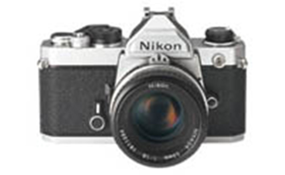
The Nikon FM (Photo) introduced at the 1977 "Nippon Camera Show" went on sale in May of the year.
At that time, Nippon Kogaku K.K. was trying to adopt an AI system for a SLR camera TTL metering system — a breakthrough that never really happened.
As it turns out, the Nikon FM became a leading product.
The AI, or "Automatic maximum aperture Indexing" system renewed, for easier TTL metering, the aperture-coupling device between a Nikkor lens and camera's exposure meter which was basically established for external metering system.
Its designers strove for backward compatibility with previous models and a coupling device to cope with the latest technology.
This made the camera historic for Nikon.
Following this, the Nikon F2 Photomic became the Nikon F2 Photomic A, the Nikomat FT2 became the Nikomat FT3 (see Part 6.), and the Nikomat EL (See Part 7.) became the Nikon EL2 (See Part 8.).
All the older models were renewed with the change to coupling devices (as mentioned in the earlier issue, the NikonEL2 metering system also marked a great change).
The Nikon FM was, above all, entirely new and designed from scratch.
It was a Nippon Kogaku's solution in line with the trend towards smaller SLR's and for request for a camera a step lower than the Nikon F2 request by oversea distributors mainly in the U.S.
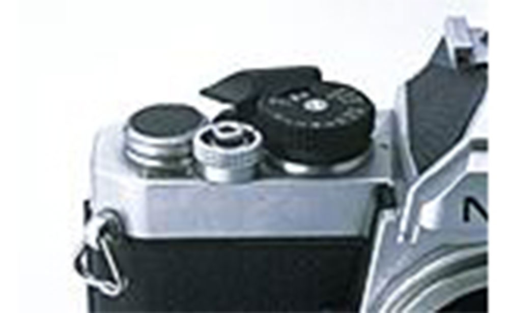
Shutter dial
The Nikon FM adopted a square-type focal plane shutter called "Copal CCS-M". This shutter unit features in that shutter speed selector cam shaft is arranged horizontally, and if coupled directly with the shutter dial, the dial goes through the camera's front panel.
This was same as in the previous "Copal Square S" shutter unit and other manufacturers actually located the shutter dial in front of the camera body.
The Nikomat series, starting with the Nikomat FT (See Part 5.), brought the dial to the lens mount area for the sake of looks, but there were arguments for and against this.
When adjusting exposure by looking through the viewfinder, the aperture ring and shutter dial are close to each other, for easy operation.
Once you get used to it, you can find out the shutter speed setting from the position of this dial's lever.
However, on the other hand, some criticized its relatively unsophisticated lens-shutter-camera-type looks.
Many people had an idée fixe that a shutter dial of a focal plane shutter should be located on top of the camera.
As a result, the FM's shutter dial was placed at the conventional position, as on the Nikomat EL, ELW, and Nikon EL2.
This arrangement requires rotating movement from the camera top's dial to the shutter unit's front cam shaft, and bending 90 degrees of the rotating direction.
The designers considered using gears, but too many gears would be needed, and the plays will not be completely eliminated. One day, an engineer suggested using a durable string. Despite skepticism, it worked just fine, without shifting or loosening, even after hard testing.
Thus, we succeded to position the shutter dial conventionally in a very simple way using a string a pulley.
Automation and VE
When the Nikon FM was being developed, camera production was undergoing drastic changes. Automation, which was applied to automobiles and watches, was also applied to efficient production of high-performance cameras at low cost, driven by rigorous standards of camera design.
Accordingly, a big change in the Nikon FM was in its mirror box.
As mentioned earlier (See Part 5.), the diecast of such Nikomat cameras as the Nikomat FT, EL, and Nikon EL2 featured unified front panel and mirror. This reduced the fabrication time and expense of metal mold, but was not suitable for automation. The complicated shape made it difficult to hold or position levers, gears, and shafts.

Therefore, the mirror box was changed to be constructed by assembling metal panels into a box shape. All parts were placed to the metal plate with auto-assembling machines and by assembling all panels together, the mirror box was made.
Also, VE (Value Engineering) was applied around this time.
All single parts were analyzed, with the objective of using fewer and cheaper parts while maintaining the same high performance. Even the Nikon FM, embodied a few design changes after its release.

The shutter button lock, for example. The initial model locked the shutter button by rotating the ring around the shutter button, but the latter model locked using the edge of the winding lever, and the ring around the shutter button was changed to a fixed type without knurling.
This applies to the Nikon FE (1978) as well, and result in a reduced number of parts.
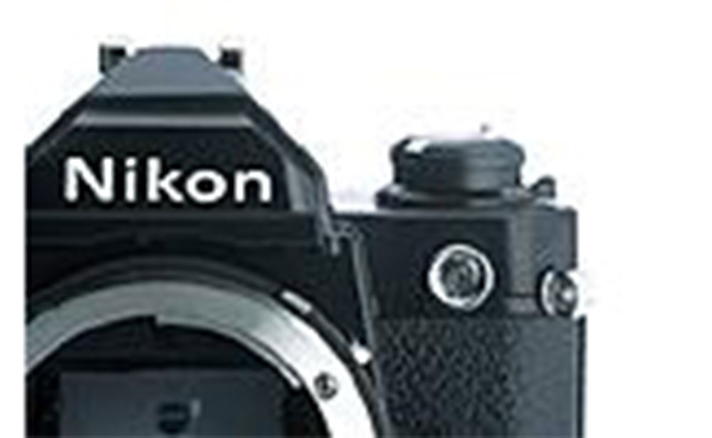
Also, the initial model had the knurled ring around the rewinding knob, whereas the latter version didn't. Film rewinding is done by a crank, so a knurled ring was not necessary for the rewinding knob.
Nevertheless, the Nikon camera had had the knurled ring for years. This change was made for reducing fablication time.
"Octopus with thirteen feet"
The metering system of the Nikon FM uses the same IC chip as the F2's Photomic SB and Photomic AS finders, but the chip package is different.
The Photomic-type uses a ceramic flat package, whereas the FM uses a round, metallic package called "TO-5" (Photo) that is like a lid-shaped metallic case with many lead lines at the bottom.
Thus, the latter package was called an "octopus".
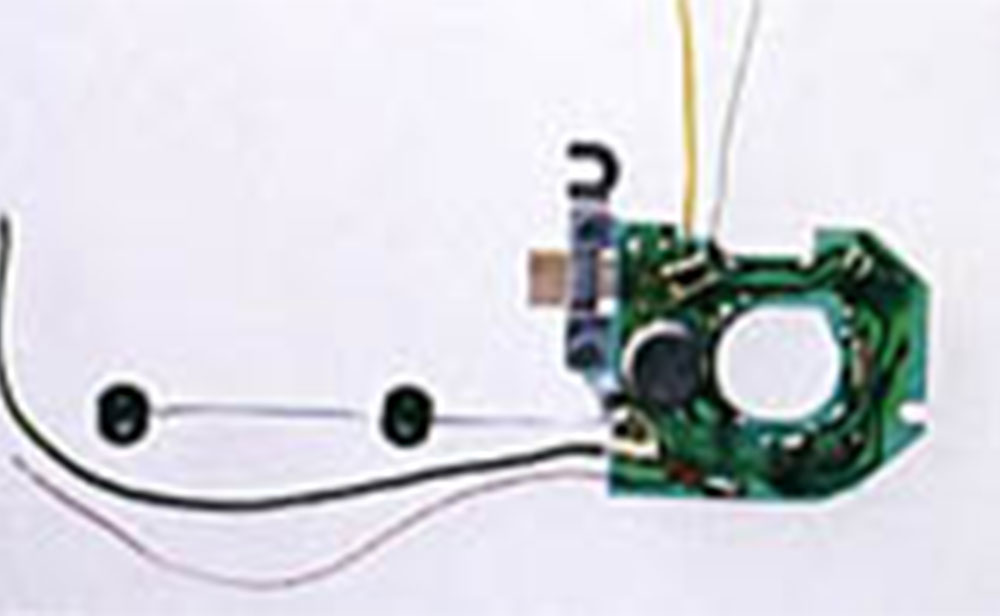
"TO-5" Metallic package of monolithic IC
is appearing on the green printed board
When designing the IC chip, this package's pin number is also taken into consideration. Due to the external circuit parts, the pin number had to be thirteen. The flat package used with the Photomic series has 16 lead lines, so there's no problem. But the "TO-5" has, at maximum, 12 pins.
After getting weary of thinking this and that, the circuit designers finally came up with one solution, by a hint of an unexpected idea, which the author suggested, "make the metallic case itself the 13th pin as the case is made of metal".
The case of "TO-5" package's small jags around the frame show the position of the pin.
But actually, with the Nikon FM, this jag is attached to a small metal rod and is soldered to the printed board.
You can say that the mouth of a twelve-legged octopus became the 13th leg.
The IC manufacturer was aware of this and actually the package passed the reliability test, but that might have been a dangerous gamble (this applies to FM only, while the FM2).
Old technology lives on
The Nikon FM was, in a sense, a state-of-the-art camera incorporating break throughs such as the AI system, downsizing, automation, VE, just to name a few, which Nippon Kogaku first applied.
The technologies experienced with the FM were inherited by later SLR models in various way. In that sense, the importance of the FM should not be underrated.
Note
This issue first appeared in "Nikkor Club Quarterly" magazine , published by the Nikkor Club, and was revised for Nikon's webpage.
Products, brands and companies names are trademarks or registered trademarks of their respective companies.
Camera Chronicle
Archives of corporate history subject matter related to Nikon cameras, including rare materials, as well as product photos of cameras and lenses.